Tuesday, October 4, 2022
Reflecting on The Story So Far....
Friday, September 30, 2022
End Fed Half Wave (EFHW) Antenna
Tuesday, September 13, 2022
Dummy Load 50 Ohm 50 Watts
I thought it would be useful to have a dummy load to take power measurements. Rather than buy one I decided to make my own (as usual!) I purchased 10 x 470 Ohm 5 Watt Metal Oxide Film resistors. They are low inductance which is very important at RF. My power is limited but I decided to make it rated for 50 Watts. 10 x 470 Ohm in parallel gives 47 Ohms nominally. Parallel connection means that the power rating becomes 10 x 5 = 50 Watts nominally. (I read one article online which stated 4 x 100 Watt resistors in series gave him 400 Watts. This is incorrect! A common mistake.) The main problem I find with most projects is the hardware, in particular, cases and enclosures. Mooching around, I found this sewing tin with a hinged lid. Using a metal enclosure ensures good screening and prevents any transmissions radiating from the unit. A quick inspection found that the SO-239 socket would just fit on the side, provided I cut the lid away to allow it to close. The metal is very thin, so care is needed when drilling the holes. Sharp drill bits and proper support whilst drilling is the key. When assembled I measured the DC resistance with a multimeter at 47 Ohms. I'm not sure how accurate my multimeter is.
Sunday, September 4, 2022
14MHz Coil Shortened Dipole
14MHz = 1.1:1
Bonus: 50MHz = 1.7:1(ATU)
I had to add about 100mm to each end to get the SWR down. This means the calculations, or the interpretation of them, was in error. The measurements were made to the centre of the coils which is probably incorrect. When tested at 50Mhz, it was found that the SWR was a useable 1.7:1. I suppose the antenna has a tuneable harmonic.
Contacts made:
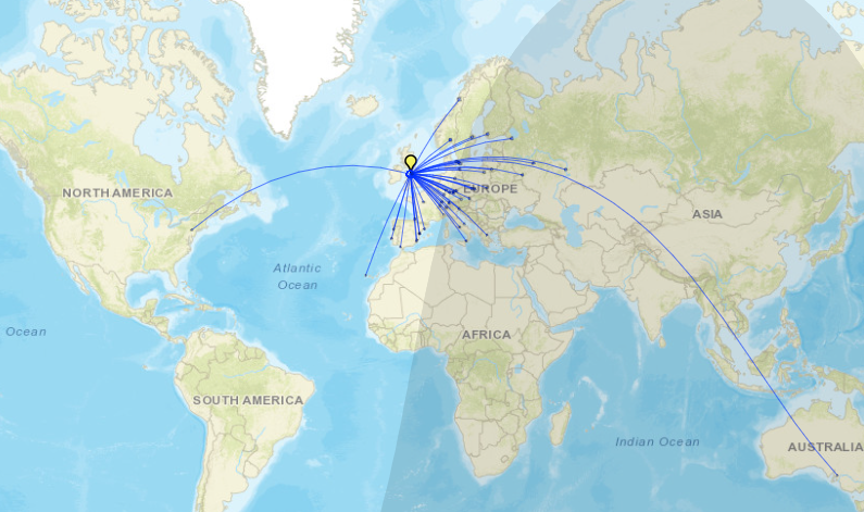
Croatia -6dB Poland -15dB Germany -11dB Belarus -12dB France -12dB
Hungary -17dB Croatia(2) -13dB Hungary(2) -11dB (All on FT8)
Spot Reports for 14.074MHz FT8:
The SWR readings achieved were to be expected. This is a single frequency antenna with a comparatively narrow bandwidth. The Inverted V angle was very large, probably greater than 120 degrees. If this antenna was erected outdoors, the performance would be much better. Loft antennas tend to perform a lot worse. It seems to be working very well though and I will keep this antenna on-line for using on a regular basis.
Saturday, August 27, 2022
Short HF Multiband Vertical Antenna M0CVO
1.8MHz - >10:1 (useless)
3.5MHz - > 10:1 (useless)
7.0MHz - 1.4:1
10.1MHz - 1.2:1
14MHz - > 2.8:1 (ATU)
18.07MHz - 2.2:1 (ATU)
21.0MHz - 1.8:1 (ATU)
24.9MHz - 2.7:1 (ATU)
28.0MHz - 1.6:1 (ATU)
50.0MHz - 1.1:1
Saturday, August 20, 2022
End Fed Random Wire Antenna for HF
After my successful build of the BBTD antenna, I started to wonder if the terminator resistor was actually needed, and if perhaps using a matching transformer would allow a lot of latitude when designing other antennas. I started to experiment and researched other antennas, in particular the Rybakov 806 design. This antenna is based on a length of wire (7.6m) that, as far as I know, is not resonant on any of the desired frequencies and is erected vertically using a matching transformer at the base. The Rybakov needs radials to perform well.
1.8MHz - >10:1 (useless)
3.5MHz - 3:1 (ATU)
7.0MHz - 1.3:1
10.1MHz - 1.4:1
14MHz - 1:1
18.07MHz - 1.8:1 (ATU)
21.0MHz - 1:1
24.9MHz - 1.1:1
28.0MHz - 1.6:1
50.0MHz - 1:1
So the SWR readings are not all that bad. As we all know that's not the full story. The length of the radiating wire doesn't seem critical, but as long as possible is best. If it can be laid out in a straight line and also as high as possible, this also helps, but is also not critical to the SWR. But does it perform? Yes and no. I can make contacts on it all over the place, again on FT8. I can't seem to make any voice contacts at the moment, no matter which antenna I use. Listening to most of the SSB conversations though they are all mainly using very high power and multi element beam antennas compared to my menial 10 Watts on a homebrew! Some of them are on anything from 400 to 1000 Watts. I can't compete with that!
One conclusion I have come to, after making some comparisons, is that these wire antennas with matching transformers are a 'Jack of All Trades but Master of None'. They cannot perform as well as a proper tuned antenna for a specific band, for example the 14MHz 'Inverted V' I have on my gable wall, but they do get the job done for people with limited space and resources. If the antennas were installed at a decent height above ground I'm sure the performance would improve dramatically, but I have no provision for that here. On to the next project which will be another antenna - vertical this time. I understand that verticals tend to give you a better 'take-off' angle for DX when propagation allows. It will be a shortened antenna because I can't have a 60 foot monstrosity in my garden!
(Update - I tried the antenna with a 16:1 transformer but made it with isolation between primary and secondary. I then shortened the radiating wire length by about 8 feet. Arguably it is working a bit better than before. The SWR hasn't changed much, if anything it has improved.)
Tuesday, August 16, 2022
Power Supply Make-over
A while ago, I built my own 30 Amp power supply after seeing how much they cost these days. It has performed flawlessly since, so I thought it was time for a make-over. The heart of the unit is an 'off the shelf' 30 Amp switch mode power supply module, cheap as chips from Amazon. At first I ordered a couple of cheap Amp and Volt meters for indication. Problem was that after a while they started to stick, especially in the hot weather, and I also couldn't get a definite reading from them. Originally, the DC terminal posts were at the front where you would normally expect to see them. I wanted them at the back out of the way for neatness, so I re-routed those. I re-hashed the box to accomodate a 20x4 LCD display and programmed a micro controller to do the work. A DS18B20 temperature sensor was also installed close to the electronics. I used an ACS712 - 30A as the current sensor. This sensor has received quite a lot of bad reviews, but I don't seem to have a problem with it. The main concerns are that the terminal connections are incapable of carrying the 30 Amps that it's rated at. Some say that it got extremely hot when passing only 5 Amps. Well I must concurr that the connections do seem a little 'puny' but I managed to get a significant sized conductor into the terminal block after prising it open a bit with a small screwdriver. I have been testing this unit for a few days now and with an intermittent current of about 10 Amps, I haven't witnessed any overheating issues. The temperature sensor will alert me to this. After a bit of messing with the calibration routines for the voltage and current, it was looking good. A couple of days of testing and tweaking, and a coat of matt black paint, now it takes pride of place in my shack. Very pleased with it!
2E0ITG and the Satellites
The title sounds like a rock band! I decided to take the plunge and sit the RSGB Intermediate examination on 10th November 2023. I passed ...
-
Ever since I saw a video of someone with this antenna operating portable on 20 Watts I have been compelled to build one. He was making c...
-
I thought it would be useful to have a dummy load to take power measurements. Rather than buy one I decided to make my own (as usual!) I pur...
-
Introduction Another branch of the hobby I have enjoyed for many years now has been detecting and decoding digital data and messages that...