Friday, November 17, 2023

2E0ITG and the Satellites


The title sounds like a rock band! I decided to take the plunge and sit the RSGB Intermediate examination on 10th November 2023. I passed and applied for my license and my new call sign is 2E0ITG. This will give me 50 Watts to play with so contacts should be much easier from now on. Also, I will be able to work extra bands including 5 MHz and some microwave frequencies, along with other privileges. I am currently looking into VHF / UHF communications for satellite work. 

 I have removed my QFH antenna from its current position in the garden and done a few minor repairs and maintenance tasks on it. It is now ready to be sited on the roof line. This antenna has been excellent for receiving and decoding weather satellites in the past. When I first constructed it, it was designed to be used as a transmitting antenna, so it should perform well. I tested it with my analyser and all looks good for the required frequencies. I will be using my UV-5R radio for this and will be limited to 5 Watts. This should be fine because you are not allowed to use high power for satellite work as it drains its power supply If you want to follow my progress you can pick it up at https://2E0ITG.blogspot.com

Monday, October 16, 2023

Introducing the SV1428 - 14 & 28 MHz Short Vertical Antenna.


Since I've been using my EFHW antenna, I haven't really felt the need for another one. Problem is that this antenna is horizontally polarised. I wonder sometimes if a decent vertical antenna might perform better on those days when contacts are hard to come by. The reason I think this is because of the disparity in signal reports I receive, when I know full well that the signal should be better. The reverse is also true - I might get a high signal report only to send a poor one back.

The main reason for not having a vertical antenna erected is because of its appearance. I try to be as inconspicuous as possible. As a compromise, I came up with this short 14 MHz vertical. After all, I was really surprised at the performance of my shortened dipole which uses the same principles. I did attempt this antenna before using a centre loading but the frequency response was way out. I must have miscalculated somewhere. It seemed to be resonating at about 9 MHz no matter what I changed - so no use for anything really!

The overall height of this antenna is 3.5m. Doesn't look too obvious if mounted a couple of metres below the apex of the roof. I didn't want to top load the antenna because it would make it top-heavy and unstable in high winds. I also wanted the loading to be above the centre mainly because, I'm led to believe by so called experts, that the first couple of metres of an antenna is where the work is done. I also needed it to be calculated properly if it was to have a chance of working on 28 MHz too. Finally, after checking, tweaking and double-checking my calculations, I came up with this design. 

To limit the number of turns required on the coil to a sensible size, I had to increase the diameter of the former to 42mm, allowing me to use only 16 turns, which also keeps the weight down. The wire I used is 2.5mm2 solid insulated household wiring cable. Hopefully this will minimise any resistive losses. All of the antenna is built using an old fishing pole for the main part. I stripped down an empty silicon sealer tube to make the reducers to match the coil tube down to the diameter of the pole, and glued in place. I also left about 1 foot of extra wire sticking out of the top to give me some trim capacity.

On to the testing. Any 1/4 wave vertical needs a good ground plane to perform. I found that two pieces of wire about 2m long stretched out in opposite directions at about 45 degrees and connected to an 8 foot aluminium ladder on top of the garage did the trick. I will add more radials later as I see fit. There may be some experimentation needed here because it can be quite finicky to get the right result into a small space. If there is enough room, you can fit full 1/4 wavelength radials which would probably be better. This antenna may also benefit from an additional ground connection. The antenna was fed by Mini RG8 coaxial lead. So first of all I connected the analyser and did a sweep from 13MHz to 15MHz to see where the sweet spot is. The excess wire at the top had to be removed as it happens.


As you can see there is a good dip of low SWR from about 13.5 to 14.8. Perfect! Any mismatch can be sorted with the ATU. A quick call on FT4 and 10 Watts got two instant responses from Germany and the Netherlands, both with positive signal reports. The SWR reading on the rig was even better than the analyser suggested. I put this down to the length of coax that was now being used. Moving on to check at 28Mhz I was pleased to see a good SWR here too, as can be seen below.


An operating range of 27.7 to about 33MHz - very useful! Once again, operational SWR was better with the rig. An even better ground plane would allow this antenna to perform to its full potential. I find it extremely difficult to compare one antenna with another. I still seem to get more contacts with the EFHW, but it does work extremely well. 


Here we can see the spot reports from Gridtracker.
More operational trials may be required under different conditions. I am going to name this antenna the SV1428. This will be my vertical option for the present time. Here it is just above the edge of the roof line.


Saturday, May 6, 2023

Free Ham Radio Software for Signal Decoding


 Introduction

Another branch of the hobby I have enjoyed for many years now has been detecting and decoding digital data and messages that are all over the airwaves. I thought it would be a good idea to list some of the excellent free software available on the internet, and share a few hints and tips. (I have included a list at the end of this article with links) It can be very satisfying knowing that you have tuned into a signal and decoded it when you were never meant to! 

RTL-SDR
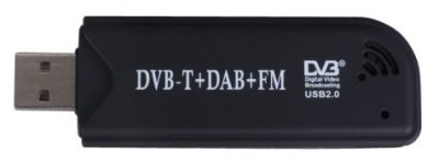
The Realtek RTL2832U Radio Tuner USB Stick By far the cheapest, easiest and most convenient way for anyone to enter into the world of radio frequency scanning is to use a USB dongle plugged into your computer. Usually referred to as RTL-SDR dongles. These cheap devices were first manufactured to receive free-to-air TV broadcasts for a computer. Some bright spark realised that by employing software to 'hack' the tuner inside, they could be repurposed as a handy radio receiver. Since then, manufacturers have cottoned-on to the idea and now they are modified and sold as RTL-SDR instead of DVB-T sticks. This means that the prices went up, but they can still be found for a modest sum. In my experiences the best ones have the RTL2832U chip. On the down side, these radios cannot compare with a dedicated scanner for sensitivity and reception, but they are less expensive. 


Uniden make a good range of dedicated scanners both home-base and portable.


Antennas

The frequencies that you wish to tune into will determine the type of antenna you will need. Alternatively, you could go with a broadband scanning antenna which will cover many frequencies, but these tend to be more expensive to purchase. like the one pictured here. However, for more specific decoding the antenna will have to be more specialised.  You can always 'home brew' an antenna, and it's surprisingly easy, the simplest being a wire dipole. There are many articles on making your own antenna on line, so I won't go into that here. The main requirement is that, if possible, get the antenna erected outside and as high as possible for best reception. Antennas do work quite well in an attic space, but it will fare much better outside.

AIRBAND & VHF

Where to start, well the list is virtually endless. Let's start with the VHF (Very High Frequency) band that everyone should be familiar with. We are all used to listening to radio stations on FM (Frequency Modulation) between the frequencies of 88 and 108 MHz. But if your radio can tune in just above this range, you will find all kinds of radio traffic. For a start, you can hear the Air Band chatter between aircraft and air traffic control on AM. Search around on this band and you will also hear some brief screeching sounds at 131.525, 131.625,131.725 and 131.825 MHz AM (Amplitude Modulation) These are the sounds of ACARS (Aircraft Communication Addressing and Reporting System) messages sent from aircraft transponders. With the correct decoder you can position aircraft on a map to do some plane spotting, if that's your thing. There are also lots of Amateur Radio operators chatting on this 2m band on FM. Also on the 2m band you will find pager communications, weather satellite transmissions, taxis and a whole lot of other stuff. Moving down to the lower limits of the rtl-sdr dongle, CB transmissions can be received between 27 and 28 MHz. This is the 10m band so a longer antenna will be required. At around 137 to 138 MHz you can hear APT (Automatic Picture Transmission) satellite transmissions from weather satellites at certain times during the day. These can be decoded into pictures that are really impressive using WXtoIMG. Your receiver must be set to receive FM at a bandwidth of about 40KHz though. Your SDR, when set up, will be able to manage this easily. This program also lets you know when they are flying over.

HF

If you have a radio receiver capable of getting the HF (High Frequency) bands, this is where the fun really starts. An SDR dongle is not capable of tuning down to lower frequencies below about 24MHz, unless it is modified in some way with a converter. On these bands you will find radio hams exchanging digital and voice communications between each other 24/7.  Morse code, FT4, FT8, RTTY and many others. HFDL (High Frequency Data Link) from aircraft can be decoded giving positions of aircraft all over the world and not just within your own country. Using HF bands increases your range for scanning. It is possible to find Stanag 4285 transmissions from NATO stations, however this is usually encrypted, except for when a test transmission is sent. The French Navy are favourites for this.
This is a decoded test signal using Sorcerer.


 WEFAX (Weather Facsimile Picture Transmission) signals can be found on several frequencies. 7.878 MHz USB finds the Deutscher Wetter Dienst WEFAX transmission. I used FLDIGI to decode it into picture format.


There really is too much to mention here because each mode is worthy of an article on its own. But its all there to be listened to with the right decoders. Some of the decoders listed here are capable of many modes. A lot of research is required to find information on how to do it, but it all depends on what you want.

Software

Here you can find links to download your free software. All the decoders here can use your sound card as a modem for decoding. If you are serious about decoding, there are many excellent non-free packages for sale that you may want to consider.
 
You will need to install a different driver for your dongle, otherwise your computer will still think that it is a DVB-T stick. Use Zadig to install the correct driver.
 
You'll be needing a software defined radio. HDSDR  is the simplest and quickest way to get going.
For HDSDR to work with your dongle you will need an ExtIO.dll file. It can be difficult to find this file and you may have to install a different package just to extract the dll. After you have installed HDSDR, find the HDSDR program folder on your computer and copy the ExtIO.dll file there or it will not work. There is a good set-up guide on this page with links HDSDR Set-Up

Another free SDR to consider is Sigmira which has a selection of decoders built-in.

If your sound card doesn't support Stereo Mix or similar, no need to worry. Just install this virtual sound card software and it will pipe the sound from HDSDR to your decoder when selected VB-Audio
 
When you finally get up and running and are ready for some decoding, it helps greatly knowing what a particular signal actually sounds like. Signal ID Wiki can help you here.
 
wxtoimg is the best software for decoding satellite images 
 
FLDIGI has a wealth of decoders built into it including WEFAX, Morse and RTTY.

If you want to decode ADS-B 1090 MHz signals for aircraft tracking try this RTL1090 . This is a stand-alone program which connects directly to the RTL-SDR dongle, so no sound card set-up required. 

You can then feed the output of RTL1090 straight into your very own Aircraft Radar with VRS
 
If you do want to work HF signals, Sorcerer is a good decoder for HFDL, Stanag and many others.

Other software you may be interested in:
WSJT-X for ham band decoding of FT4, FT8 etc.
MSHV same as above.
PDW for ACARS and pager decoding.


Tuesday, October 4, 2022

Reflecting on The Story So Far....


Since acquiring my Amateur Licence in June this year, I have accumulated a few bits and bobs, and lost a few quid! It makes me wonder what it will be like a few years down the line! My (untidy) set-up can be seen above. Simple but effective. The Icom IC-7300 has many features built-in which reduces the number of accessories I need. The computer takes care of the rest. I bought a SWR / Power meter because I wanted a second opinion on the power output, but it turns out I could have saved myself some money. The readings always correlate. It will come in useful though for doing remote power readings with the dummy load. The Nano-VNA has been a good investment. It has proved very useful for testing antennas, baluns, ununs and transformers. The power supply upgrades are a triumph, giving me important feedback on power supply parameters.

I have made several antennas, but as the hobby dictates, you are never satisfied with what you have. I like to make my own gear where possible because of the learning experience. The EFHW antenna has been marvellous. I am making contacts as far away as Africa, South America, USA, Australia and New Caledonia. You soon learn that the simplest solutions are usually the best. The search for constant improvement goes on. I am enjoying the hobby so far, but the dream would be to have plenty of space to erect a tower and have an array of antennas high up. Perhaps a move to the countryside?


I think the power allowance for Foundation Licence holders at 10 Watts is too low. I mean, even users of the Free Band on 27MHz are allowed 12 Watts SSB with no licence required! It is a struggle to get a voice QSO at all! I understand that the need for reducing interference is critical, but if you cause interference, no matter how much power you are using, you are obliged to put it right. Most foundation licence holders have usually had a good grounding with CB etc. so its not like they are coming in totally green. Modern TV's and other equipment is far less prone to RFI these days anyway. It seems I am consigned to using digital for weak signals for the time being. I may look into upgrading my licence to Intermediate next year, just so I can operate with a better power level.

Friday, September 30, 2022

End Fed Half Wave (EFHW) Antenna


 Ever since I saw a video of someone with this antenna operating portable on 20 Watts I have been compelled to build one. He was making contacts all over the place with it just slung over a couple of trees. This is a 1/2 wave resonant antenna for 40m, but should also be good at the harmonic frequencies too, making it somewhat multiband. There are lots of resources on line about these antennas and I recommend some research is done before attempting the build. The 49:1 unun in particular needs to be studied because it isn't straight forward. The 9:1 and 16:1 ununs and transformer types I have employed before will not suffice for this project. They will be too lossy and inefficient at this ratio with a resonant antenna.  Capacitors need to be employed to improve SWR and performance on the higher bands. (counter-acting the inductance at higher frequencies)


(Diagram of 49:1 unun)

I am only using low power so just one toroid core should suffice. It seems that the higher the power, the more cores you will need, and the transformers can get hot. I have seen people opt for the FT240-31 core, but after researching the differences between type 31 and type 43, I decided to go with the recommended type 43 core. The capacitor required is a 100pF high voltage type which I found to be expensive compared to the 220pF of similar spec. I acquired some 220pF 15kV ones. If I connect two in series the capacitance will be halved and the working voltage will be doubled resulting in a 110pF at 30kV rating (belt and braces). Also, if your wallet allows, the theory is that using two toroids makes the transformer more efficient, especially at lower frequencies. Your choice. Theory also dictates that a good ground is required, however, with the right length of coax, the coax screen can act as a counterpoise because the current flow will be minimal at resonance. Some experimentation is required here. It might be that a counterpoise wire will be required on the ground connection, anything from 1m to 10m long. A good ground plane system can also be used if available. My finished project can be seen below.


I am assuming it will be good up to 50 Watts, but if the SWR drifts at higher power, this could be a sign of over-heating.


The box will have to be at least 100mm square. Mine is about 115mm square. There is a terminal post on the left for the antenna radiator. 
A link was made to a terminal post on the right to accomodate a ground / counterpoise connection.The two capacitors can be seen connected at the SO-239 socket, with some hot glue as a make-shift insulator on the joint.  I have left two large holes at the bottom for cooling / ventilation. I need to cover these with some kind of gauze to keep nasties out. I initially intend to house the box indoors. Just needs the 20m radiator wire erecting and we should be good to go. I want to construct a pulley and weight arrangement at the far end of the wire to maintain tension and prevent breakage in high winds.

Results and Testing

I can just fit a 20m wire from near the top of the roof to the diagonal corner of the garden. There is about 3m of radiating wire in the loft making connection to the box and counterpoise. A post was erected in the corner with the pulley attached at the top.


A piece of nylon rope was threaded through the pulley and connected to the wire.


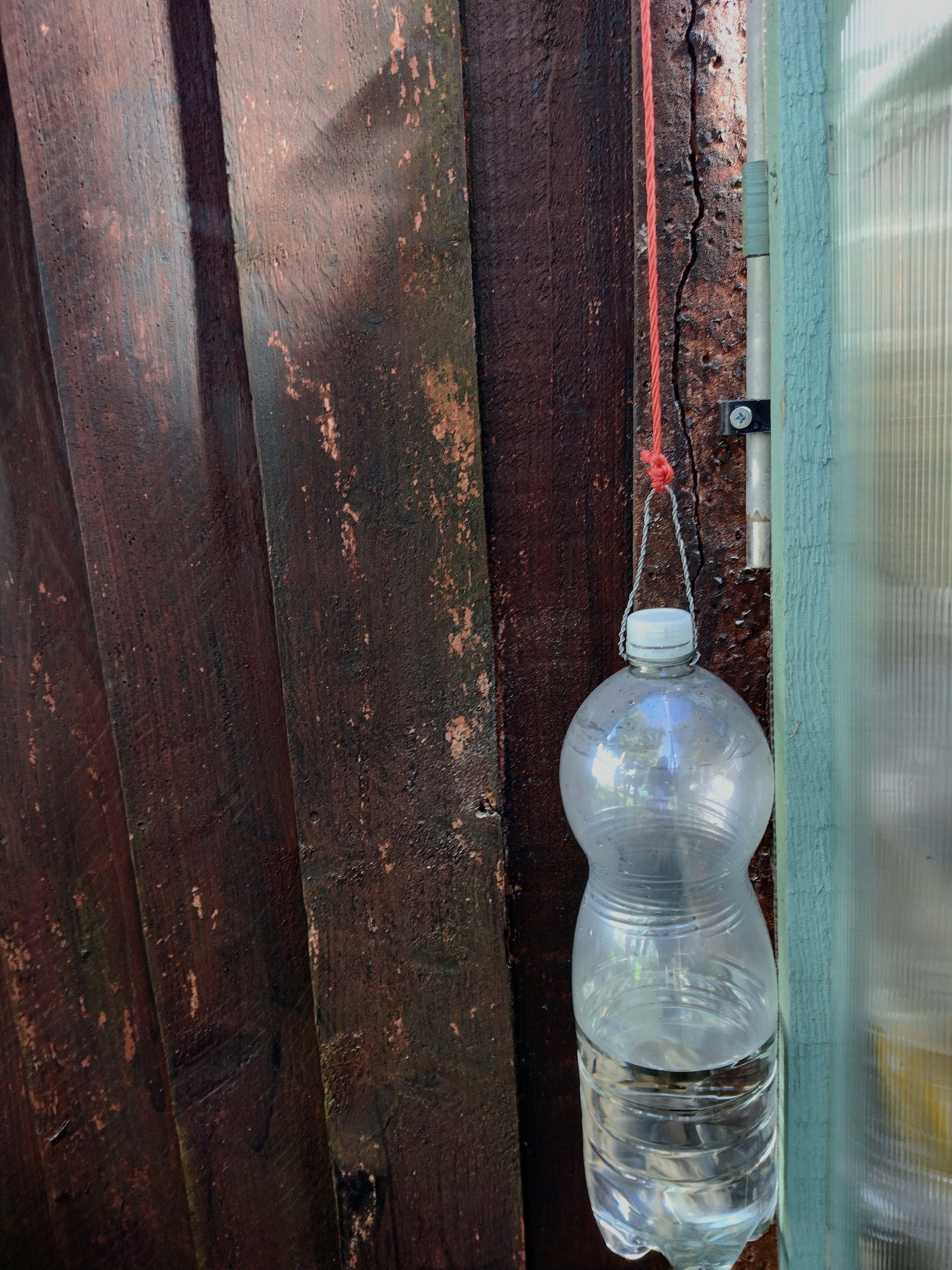
The weight, a plastic bottle with just enough water to hold the wire tight, was tied to the rope and tension was achieved.


The theory is that any extra tension on the rope from high winds, temperature expansion / contraction or perching birds will allow the weight to rise and fall accordingly, relieving the strain on the wire. I think the antenna would perform much better if higher from the ground. At the moment it stands at about 12 feet at its lowest, rising to about 25 feet. 

Results

After experimenting with various counterpoises, 2m, 3m and longer lengths, I settled on a 1m length of wire. I really didn't know where to check the SWR for adjusting, so I decided to check at 14MHz, which is a full wavelength. The reading was about 1.5 after snipping about 6 inches off the radiating wire. Further cutting of about 2 inches caused the SWR to rise a small amount, so I decided not to trim the wire any more. I also experimented with varying the capacitance value from 220pF to 110pF, 73pF and no capcaitor at all. Some interesting and weird results were obtained. Using 220pF flattened the SWR peaks, but raised the overall SWR over the bands. 73pF raised all the readings. So I settled with the design spec of 110pF. At one point I was also getting gradually rising and falling SWR values at the higher frequencies which I couldn't explain. I guess it was something to do with changing the capacitor values, or a dodgy solder connection. The analyser results pretty much reflect the results from the radio SWR readings. Obviously, looking at the graphs, the SWR will be lowest where the impedance is 50 ohms.

(Analyser results - 1.8MHz to 30MHz sweep)

Final SWR Readings

1.8MHz = 2.9
3.5MHz = >10 (useless)
  7MHz  = 1.9
10MHz  = 1.6
14MHz  = 2.1
18MHz  = >10 (useless)
21MHz  = 2.2
24MHz  = 3
28MHz  = 1.7

Conclusions

The final results I obtained are far from perfect with respect to SWR, but the antenna is very effective when used with the internal ATU. It was immediately apparent that the received signals sounded much better and clearer compared to my other antennas. It would also seem that the antenna works better at long distances rather than closer to home, judging by the signal reports. Contacts with USA for example, are much easier to get now, but I can still make contacts across the UK. I will have to do without the 3.5 and 18MHz bands for now until I come up with a solution. The problems must lie with the transformer build. I might try a different approach in the future. Generally very impressed with this antenna, once again proving that the simplest methods are usually the best. 
 
 
Update - September 2023

Just for the hell of it I decided to take apart the 49:1 unun and add another ferrite core to see if there would be any difference. Apart from a possible increase in power handling ability, its hard to see any real improvement with performance. No improvement with the higher SWR readings on the lower frequencies. However, I can now tune the 18Mhz band. I found a small improvement by disconnecting the counterpoise. I also noticed that after moving things around in the loft, there was a change in readings. This reinforces the fact that you shouldn't have any objects close to your antenna. My situation isn't ideal because part of my antenna is in the loft! On the positive side, all the frequency bands above 3.5MHz fall below the 3:1 threshold. This is still my best performing antenna. So my advice would be that if you are only running up to about 50 Watts, then I think you would be OK with just one ferrite. Above this, you probably need two. Below is the full band sweep from the antenna analyser.


Tuesday, September 13, 2022

Dummy Load 50 Ohm 50 Watts


I thought it would be useful to have a dummy load to take power measurements. Rather than buy one I decided to make my own (as usual!) I purchased 10 x 470 Ohm 5 Watt Metal Oxide Film resistors. They are low inductance which is very important at RF. My power is limited but I decided to make it rated for 50 Watts. 10 x 470 Ohm in parallel gives 47 Ohms nominally. Parallel connection means that the power rating becomes 10 x 5 = 50 Watts nominally. (I read one article online which stated 4 x 100 Watt resistors in series gave him 400 Watts. This is incorrect! A common mistake.) The main problem I find with most projects is the hardware, in particular, cases and enclosures. Mooching around, I found this sewing tin with a hinged lid. Using a metal enclosure ensures good screening and prevents any transmissions radiating from the unit. A quick inspection found that the SO-239 socket would just fit on the side, provided I cut the lid away to allow it to close. The metal is very thin, so care is needed when drilling the holes. Sharp drill bits and proper support whilst drilling is the key. When assembled I measured the DC resistance with a multimeter at 47 Ohms. I'm not sure how accurate my multimeter is.


I assembled the project in about 2 hours. The tin made for a neat compact unit. everything just fit inside really snug. Total cost was about £6.00. A lot cheaper than the commercial ones and it is rated at 50 Watts.


The resistors were all soldered onto 2 pieces of solid copper wire and covered with heat shrink sleeving. A bit of hot glue secured everything in place. The hot glue you can see on top is covering the centre feed wire to the SO-239 to prevent any accidental short circuits. The ground wire was attached via a small crimp-lug and bolted to the holding screw. On reflection, I could have put some sleeving over the wires. I've tested it up to 20 Watts on all HF frequencies and the SWR reading does not change from 1:1. If operating at higher powers, the tin could be filled with dry sifted sand to dissipate heat, and then sealed up.

Update:
I did fill it with sand and seal it up because I noticed that it got quite warm when testing up to 25 Watts. Hopefully, problem solved.


Sunday, September 4, 2022

14MHz Coil Shortened Dipole


 After a multitude of antenna builds using other people's designs, I thought it was time I designed my own from scratch. I decided a single frequency would be best to start with so I chose 14MHz because of the amount of traffic on this band. I think it's so popular because the antenna size is not too large to construct especially in a confined area. I looked at trap dipoles and the like and the art of shortening using coils. My final design would be a 6 metre long dipole so that it could be formed into an Inverted V to join my nest of dipoles in the loft. The coils were calculated for a 20mm former and came out at 6.68uH - 25 turns of 1.13mm diameter insulated solid copper wire, at 14.15MHz centre frequency. I decided to centre load the elements.

Testing

14MHz = 1.1:1

Bonus: 50MHz = 1.7:1(ATU) 

I had to add about 100mm to each end to get the SWR down. This means the calculations, or the interpretation of them, was in error. The measurements were made to the centre of the coils which is probably incorrect. When tested at 50Mhz, it was found that the SWR was a useable 1.7:1. I suppose the antenna has a tuneable harmonic.

Contacts made:

Croatia -6dB    Poland -15dB    Germany -11dB    Belarus -12dB    France -12dB

Hungary -17dB    Croatia(2) -13dB    Hungary(2) -11dB  (All on FT8)

Spot Reports for 14.074MHz FT8:


Conclusions

The SWR readings achieved were to be expected. This is a single frequency antenna with a comparatively narrow bandwidth. The Inverted V angle was very large, probably greater than 120 degrees. If this antenna was erected outdoors, the performance would be much better. Loft antennas tend to perform a lot worse. It seems to be working very well though and I will keep this antenna on-line for using on a regular basis.


Saturday, August 27, 2022

Short HF Multiband Vertical Antenna M0CVO


 So what do we need to do to get the length of an antenna down? Well it needs to be coil loaded. This build was originally published by M0CVO who apparently made this antenna, the HFC3015-V, commercially in the past. It is supposed to be good for 7MHz through to 28MHz with the help of an ATU. I have put my own 'spin' on it here and there though. It reminds me of the Firestick and DX27 antennas we used back in the CB days. We will need a 4:1 unun for this project and I stood by my tried and tested KISS Balun type of auto transformer. You can make your own unun or purchase one if preferred. You will also need 13.6m of 1.5mm insulated stranded copper wire. To create the coils I cut two  pieces of 41mm O.D. plastic pipe - top coil = 230mm long and bottom coil = 80mm long. Then drill 3mm holes in the pipe at the correct spacings - 220mm for top coil and 70mm for bottom. The wire can be passed through these holes to maintain the correct spacings and secure the wire in place. Keep all the coil turns in the same direction. For the main supporting tube I used a couple of fat sections of fishing pole to make about a 2m long piece. The pole sections were selected to fit the 41mm pipe pieces over and reduced the total weight as opposed to using 41mm pipe straight through because the type I had was quite heavy. You could just use a full length of lightweight 41mm pipe or any other support pole you have. They were a bit slack on the pole but the ubiquitous hot glue gun was called into action and the sections were glued together in the right places. The recommendations for the ground connection is unclear and varies from ground rod, counterpoise and/or radials from 4ft long to 30ft long. This may be where we have to experiment a bit. I initially made this antenna and stood it up at an awkward angle in the loft next to all kinds of stuff. Not an ideal situation, however the SWR readings looked promising. This is why I decided to proceed with the build. 

Testing

(The HFC3015-V, mounted and in use)

The antenna was erected outdoors on the gable wall about 10 to 12 feet high. The feed line was RG-8 Mini coax about 10m long, up to the loft and into my shack which is upstairs in my home (not ideal). The SWR readings can be seen below:

1.8MHz - >10:1 (useless)

3.5MHz - > 10:1 (useless)

7.0MHz - 1.4:1

10.1MHz - 1.2:1

14MHz - > 2.8:1 (ATU)

18.07MHz - 2.2:1 (ATU)

21.0MHz - 1.8:1 (ATU)

24.9MHz - 2.7:1 (ATU)

28.0MHz - 1.6:1 (ATU)

50.0MHz - 1.1:1

Conclusions

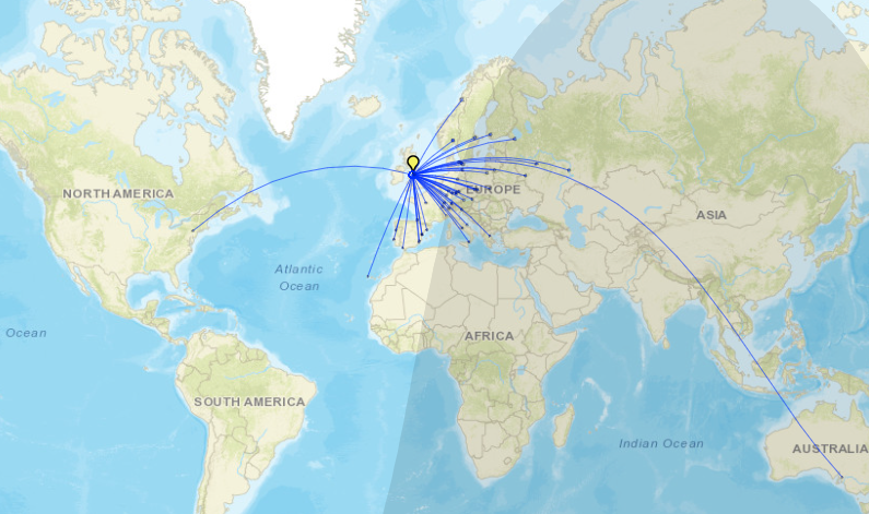
After experimenting with various ground plane wires, I couldn't get a decent SWR across these bands without grounding it to the water pipes, since creating a separate isolated ground would be too far away. Please don't use this grounding method as a long term solution as you could get stray currents flowing into your household appliances and RFI problems. This antenna only claims to cover 7 to 28MHz. Maybe with lots of messing about you can get it better than me, especially if you make the transformer a different way. I did make some contacts across Europe, but no real long distance as yet. My signal is being seen as far away as Australia though! On the plus side, the antenna is very compact at only 2m high, and is quite discrete when erected. It's quite easy to construct, cost effective and it works. Your experience of building this antenna could result in better outcomes. I intend to come back to this project to see if it can be improved. Below you can see spot reports generated by GridTracker that shows my signal reach for my antennas for comparison. I realise this is not a definitive test because of varying propagation, frequencies and conditions, but I just wanted to get an idea of the directions and reach of the antennas.

(Long Meander Wire Spots Report - seems to be greater East & West coverage)

(14MHz Inverted V Spots Report - seems to be greater West coverage)

(Multiband Short Vertical Spots Report - someone heard me in Australia?)


I cannot draw any definite conclusions from these spot reports really. I just wanted to compare a vertical with an IV and horizontal. Antennas are a mysterious and wonderful thing!

                                        (Oops! There's that Ozzy connection again. Interesting...)


Saturday, August 20, 2022

End Fed Random Wire Antenna for HF


 After my successful build of the BBTD antenna, I started to wonder if the terminator resistor was actually needed, and if perhaps using a matching transformer would allow a lot of latitude when designing other antennas. I started to experiment and researched other antennas, in particular the Rybakov 806 design. This antenna is based on a length of wire (7.6m) that, as far as I know, is not resonant on any of the desired frequencies and is erected vertically using a matching transformer at the base. The Rybakov needs radials to perform well.

I do not profess to know exactly what or why I am doing these experiments, but that's exactly what they are to me - experiments!
My experiments used the 9:1 matching auto-transformer of the KISS Balun type. It is technically not a balun but an impedance matching auto-transformer. The transformer can be constructed using two ferrite beads large enough to pass the wire windings through. I used 1.5mm stranded wire so the holes need to be about 6 to 8mm diameter. Bind the two ferrite beads together with tape and/or cable ties to form a 'binocular' style ferrite. A better solution for the core would probably be a FT240-43 toroid and wound accordingly for a 9:1 ratio. I attached a completely random length of wire which meanders all over the place through the garden on the fence (approx 140 feet long) which is horizontal for most of its length. The ground connection was made via approximately 33 feet of wire (later shortened to about 8 feet) connected to a cold water feed pipe. Although using this method of grounding is frowned upon, it was the most convenient earth at the time. Please don't use this grounding method as a long term solution as you could get stray currents flowing into your household appliances and RFI problems. I didn't think for a minute that it would work with any usefulness, but you know, you have to get these ideas out of your head! The SWR readings can be seen below:

1.8MHz - >10:1 (useless)

3.5MHz - 3:1 (ATU)

7.0MHz - 1.3:1

10.1MHz - 1.4:1

14MHz - 1:1

18.07MHz - 1.8:1 (ATU)

21.0MHz - 1:1

24.9MHz - 1.1:1

28.0MHz - 1.6:1

50.0MHz - 1:1

So the SWR readings are not all that bad. As we all know that's not the full story. The length of the radiating wire doesn't seem critical, but as long as possible is best. If it can be laid out in a straight line and also as high as possible, this also helps, but is also not critical to the SWR. But does it perform? Yes and no. I can make contacts on it all over the place, again on FT8. I can't seem to make any voice contacts at the moment, no matter which antenna I use. Listening to most of the SSB conversations though they are all mainly using very high power and multi element beam antennas compared to my menial 10 Watts on a homebrew! Some of them are on anything from 400 to 1000 Watts. I can't compete with that!

One conclusion I have come to, after making some comparisons, is that these wire antennas with matching transformers are a 'Jack of All Trades but Master of None'. They cannot perform as well as a proper tuned antenna for a specific band, for example the 14MHz 'Inverted V' I have on my gable wall, but they do get the job done for people with limited space and resources. If the antennas were installed at a decent height above ground I'm sure the performance would improve dramatically, but I have no provision for that here. On to the next project which will be another antenna - vertical this time. I understand that verticals tend to give you a better 'take-off' angle for DX when propagation allows. It will be a shortened antenna because I can't have a 60 foot monstrosity in my garden! 

(Update - I tried the antenna with a 16:1 transformer but made it with isolation between primary and secondary. I then shortened the radiating wire length by about 8 feet. Arguably it is working a bit better than before. The SWR hasn't changed much, if anything it has improved.)

Tuesday, August 16, 2022

Power Supply Make-over


A while ago, I built my own 30 Amp power supply after seeing how much they cost these days. It has performed flawlessly since, so I thought it was time for a make-over. The heart of the unit is an 'off the shelf' 30 Amp switch mode power supply module, cheap as chips from Amazon. At first I ordered a couple of cheap Amp and Volt meters for indication. Problem was that after a while they started to stick, especially in the hot weather, and I also couldn't get a definite reading from them. Originally, the DC terminal posts were at the front where you would normally expect to see them. I wanted them at the back out of the way for neatness, so I re-routed those. I re-hashed the box to accomodate a 20x4 LCD display and programmed a micro controller to do the work. A DS18B20 temperature sensor was also installed close to the electronics. I used an ACS712 - 30A as the current sensor. This sensor has received quite a lot of bad reviews, but I don't seem to have a problem with it. The main concerns are that the terminal connections are incapable of carrying the 30 Amps that it's rated at. Some say that it got extremely hot when passing only 5 Amps. Well I must concurr that the connections do seem a little 'puny' but I managed to get a significant sized conductor into the terminal block after prising it open a bit with a small screwdriver. I have been testing this unit for a few days now and with an intermittent current of about 10 Amps, I haven't witnessed any overheating issues. The temperature sensor will alert me to this. After a bit of messing with the calibration routines for the voltage and current, it was looking good. A couple of days of testing and tweaking, and a coat of matt black paint, now it takes pride of place in my shack. Very pleased with it!

(Update - After experiencing an accidental short circuit on the PSU, I have decided that I need to have some physical protection on the output, like a fuse. The unit itself has short circuit protection but I don't trust it. My monitor registered a maximum current of 35.8 Amps, if even only very briefly. This could be dangerous and a fire hazard. I intend to install a fuse to be sure, ASAP).


Sunday, July 31, 2022

International Performance


(Screen grab of logged contacts from GridTracker)


It's been a busy week with the radio, testing out the BBTD antenna. I really could not have expected anything like the results I've had. A quick search around the bands revealed the propagation was in and out for voice contacts, so I stuck to digital FT8. Also, at weekends I find it difficult to find casual users of the bands because they all seem to be swamped with contests. FT8 digital is designed for weak signal communications so I don't know precisely what I am achieving here. I started off making lots of contacts around continental Europe. I do have a limit on the power I can use, so even these contacts were remarkable to me. I could see markers popping up in USA, Africa, Brazil and South Asia which I thought were out of reach for me. However, one day I decided to persist with trying to contact them and it started to pay off. Finally, by the end of this week I had managed to contact USA several times, Brazil and even Japan (I really have put some hours in though!). The map above shows all the contacts I have made. You can also check them out on my contacts page in detail. Good luck with your DXing.


Tuesday, July 26, 2022

Terminated Dipole Update


The design and layout has changed somewhat from my original proposals. I found that I had to take up some slack with the wire lengths. I decided to change the direction through the garage to avoid close proximity with the neighbour's satellite coax cables. In total there is about 240 feet of wire in the antenna, 120 feet each leg. Re-routing the remainder around the loft perimeter sorted that out.

Ok so the antenna performed well, but I had to avoid those frequencies above about 18MHz. The SWR from 1.8MHz through to 14MHz was absolutely fine, below 2:1. It was really bugging me why I couldn't operate on the higher frequencies. So I decided to delve deeper into the problem. After much researching, I came across the KISS 16:1 balun. This was the only thing I hadn't deployed in this project. My transformer arrangement comprised of 20 turns x 5 turns of wire through the ferrites. The KISS design is much simpler employing just one coil of 4 turns, with a tap on the first turn for the 50 Ohm feed point. This is a link explaining the KISS balun. http://hflink.com/antenna/#BALUN

Because of the reduced number of turns, I could use much thicker wire (1mm sq).  Wow! Big difference. I can even tune the antenna on 50MHz. It has cost me the 1.8 MHz band but I rarely use that anyway except to listen to AM broadcasts. I couldn't resist testing on 144 and 430MHz. OMG. It works ok on these frequencies too.

Here is a quick summary of the SWR readings I got on each band:

50MHz - 1.4:1

28MHz - 2.4:1 

24.89MHz - 1.2:1

21MHz - 1.5:1

18.068MHz - 1.4:1

14MHz - 1.7:1

10.11MHz - 1.5:1

7MHz - 1.7:1

3.5MHz - 2.4:1

1.81MHz - OFF SCALE > 10:1

Let's face it. We all know that a dummy load has a perfect SWR, but it's a complete waste of time as an antenna! But overall I can recommend building this antenna as an all-rounder, or fall-back antenna. It seems to perform well, but I have nothing to compare it to really. All I know is that it is much more practical than the 1/2 wave 10m horizontal dipole in the loft, but when listening to voice transmissions, it does seem to lose the audio quality and clarity that you get with a normal dipole. Because I haven't had a voice QSO on it yet, I don't know how well it 'gets out'. The high readings on 28 and 3.5MHz could not be determined, however the on-board ATU of the IC-7300 dealt with this adequately. I feel I have accomplished what I set out to do in building a multi-band and stealthy HF antenna (and a bonus VHF/UHF too). I am getting contacts all over Europe on FT8 and 10 Watts of power on multiple bands, but as yet, not tested on SSB voice. I feel another antenna build coming on. So on to the next project.............

Thursday, July 21, 2022

Broad Band Terminated Dipole


 The antenna that I started to build a few weeks ago has now been roughly strung out around the perimeter of the garden. My main aim is to be as stealthy as possible. The two lengths of wire together add up to about 132 feet. I connected it all up and plugged it into my analyser. I was really delighted with the SWR readings. from 1MHz up to about 23MHz the readings were very good - all below 2 and as low as 1.2 on the lower frequencies. Beyond this frequency, the reading starts to creep up until on 10m band it is just over 3. I am not worried about this at the moment because I intend to lengthen each leg of the antenna up the gable end to the roof and also tidy up the run in the garden, particularly away from metal objects and such. This should add about 100 feet to the total length bringing it up to a total of about 230 feet. The final SWR reading can then be determined.

Monday, July 18, 2022

FT8 and RTTY


I have been deliberating about it for weeks but I finally bit the bullet and bought an Icom IC-7300. It does everything I need and even more. I still haven't been able to get around to erecting my multi-band antenna yet because of the searing heat we are experiencing at the moment. I can operate on 10m so I set up to do some FT8 QSO's just to try the rig out. It took me a couple of days to get to grips with this rig because it does so much - there are hidden menus everywhere. Once I had set up and turned the power down to 10W, I jumped straight in with the FT8 and made 4 contacts almost immediately on 28.074MHz, 1 in Germany and 3 in Spain (see the Contacts page). Not bad for 10 Watts running on a 10m 1/2 wave horizontal wire dipole in the loft. I am using MSHV for the decoding and transmitting.

Just out of interest, I dug this info up from somewhere, I forget where from at the moment. It lists the dB signal and correlates them with the S numbers:

-26 = NOISE FLOOR
-20  = s1
-14  = s2
-8    = s3
-2    = s4
+4   = s5
+10 = s6
+16 = s7
+22 = s8
+28 = s9

 Next I turned my attentions to RTTY and Wefax. Again on the same antenna. I found a German weather transmission for RTTY on about 10.1MHz and a German Wefax station at 7.878MHz (Deutscher Wetterdienst). I used Fldigi for the decoding here. The results were a bit scratchy but as a proof of concept, it all seems to work. The poor images could be due to the incorrect antenna for the job and the fading signal.


2E0ITG and the Satellites

  The title sounds like a rock band! I decided to take the plunge and sit the RSGB Intermediate examination on 10th November 2023. I passed ...